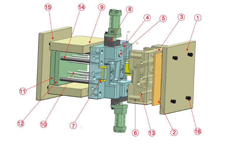
| Item | Description | Function |
| 1 | Top clamp plate | To connect the compression mold with the hydraulic equipment during compression molding. |
| 2 | Thermal baffle/Thermal insulation board | In order to avoid the temperature transfer to the pressure equipment and damage other hydraulic components. Also to reduce the heat loss during working time, save energy during compression molding. |
| 3 | Cavity plate | A steel device to mold a molding material into a certain shape, another section in compression mold that different from core plate, generally refers to the front side, is always with a sprue bush, which is the entrance for molten fiberglass. |
| 4 | Core plate | A steel device to mold a molding material into a certain shape, the section in compression mold that is engaged in opening / closing movement is called a core plate, generally refers to the rear side, will always leaves a trace on a part as it has an ejector pin to push the part. |
| 5 | Stop block/Arresting stop/ | To prevent the mold from closing especially when material is not enough for sufficient molding, protect the surface of compression mold. |
| 6 | Guide pin/Guide pillar/leader pin | Provide vertical guide to cavity and core before mold is closing, as an preparation work to ensure good condition so that verticle guiding plate can work better during compression molding. |
| 7 | Verticle guiding plate | Provide accurate vertical guide to avoid any laterodeviation when mold is closing, necessary accessory to keep better precision control for compression molding. |
| 8 | Core Pulling System | Provide auxiliary molding for partial areas which are not in the vertical demolding direction, such as the side opening during compression molding. |
| 9 | Spacer parallel/Supprort block/Spacer block | To increase the height of the mold, leave more space for Ejection System for better compression molding. |
| 10 | Ejector pin | Pushing Your Parts Around,Ejector pins are the bouncers of the injection molding world. They apply a force to eject a part from the mold after compression molding is finished. |
| 11 | Ejector plate | Provides a backer plate for retaining the Ejector, Return, and Sprue Pins during compression molding. The underside of the Ejector Plate is where the Knockout Rods from the Press touch, and make the Ejector sub assembly move to eject the part(s) |
| 12 | Ejector pin cover plate | Plate next to the ejector plate, connect with ejector pin, return pin, used for fixing the ejector pin when compression molding. |
| 13 | Heating system | Make the material in a liquid state under high temperature when compression molding. |
| 14 | Return pin/push-back pin | Necessary components for compression mold, to return the entire Ejector Sub assambly to th ehome position. If Return Pins were not utilized, the ejector sub assaembly would be returned via Ejector Pins, this would damage the end of the ejector pins and would alter the appearance the part. |
| 15 | Bottom clamp plate | To connect the mold with the hydraulic equipment during compression molding, same as top clamp plate. |
| 16 | Screw | Fix components to get a final compression mold. |
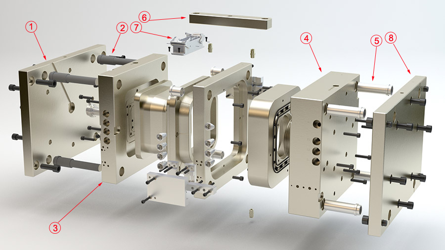
| Item | Description | Function |
| 1 | Top Clamp Plate | A part of platens in injection mold. During injection molding, the mold core and mold cavity will be mounted to the mold base, which is then fixed to the platens inside the injection molding machine. It refers to a large plate onto which a mold half is mounted. A larger machine typically has larger platen dimensions and can therefore accommodate a larger mold. Top clamp plate is located on the stationary side of the press, it provides a means to attach the locating ring to the mold base. |
| 2 | Sprue puller/sprue lock pin | To “pull” the material from the sprue bushing at the end of the injection molding cycle. The location of the sprue puller pin is directly below the sprue bushing, it is retained via the ejector retainer and ejector plates and passes through the support and retainer plates. |
| 3 | Cavity plate | The front half of the injection mold, mounted to a stationary platen and aligns with the nozzle of the injection unit. they typically have holes for Ejector Pins. |
| 4 | Core plate | The rear half of the injection mold, mounted to a movable platen, which slides along the tie bars. It provides the negative image of the desired part that will appear on rear side of the mold above the parting line when injection molding. The cavity steels contains the gate, and usually a small portion of the runner system. |
| 5 | Guide pillar/Guide pin/leader pin | Align both halves of the injection mold at the Parting Line. It always aligns with the guide bushing to ensure the position of mold cavity and mold core, keep better precision during injection molding. |
| 6 | Bonding structure | To bond the mold cavity and mold core for injection molding. |
| 7 | Hot runner temperature control junction box | To keep the temperature and heating contorl for hot runner during injection molding. |
| 8 | Bottom clamp plate | A part of platens in injection mold, silimar function as top clamp palte. |
Compared with traditional fuel vehicles, the lightweight of electric vehicles is more important. S……
Condition Description Reasons Solution 1 The Fiberglass Compression Molding part is slightly ……
/wp-content/uploads/2019/07/Mould-Flow-Analysis-Report-for-Plastic-Injection-Molding-1.mp4 Autode……
We, Shanghai Olimy Co., Ltd. is the supplier for plastic injection molds&parts,carbon fiber parts,fiberglass products, including parts made via hand lay up, RTM, SMC(compression moulding) processes.